Powered by Smartsupp

IBM ELM for
Automotive Industry

ASPICE ISO 26262

Car Icon

Automotive Certification Standards - Software Solutions

Within the automobile industry, functional safety as a process is based on the guidelines specified by ISO 26262, an international safety standard for automotive.

This page describes how we help customers by using the best practices and IBM Tools to achieve compliance in the automotive industry.

ISO 26262 Process Support

ISO 26262 standard defines functional safety as the “absence of unreasonable risk due to hazards caused by malfunctioning behavior of electrical/electronic systems”.

For ISO 26262 compliance; a functional safety consultant identifies and assesses hazards (safety risks). These hazards are then categorized based on their criticality factor under the Automotive Safety Integrity Level (ASIL) under ISO 26262. Such a clear classification of hazards helps to :

  • Establish various safety requirements to mitigate the risks to acceptable levels
  • Smoothly manage and track these safety requirements
  • Ensure that standardized safety procedures have been followed in the delivered product.
Process icon from cog, list and databases

The IBM Rational Solution for Automotive Engineering - ISO-26262 is a set of best practices to help organizations develop products that must comply with the ISO-26262 functional safety standard.

The scope of these practices covers areas that are described by ISO-26262, relating to the management of functional safety, concept, system engineering, and software development. They have been developed to support the incremental adoption of processes, practices, and tools, thereby reducing the time to value for process improvement initiatives.

Learn by watching videos

ASIL and its Support with IBM

The safety lifecycle of any automotive component, within the ISO 26262 standard starts with the definition of the system and its safety-criticality at the vehicular level.

This is done through hazard analysis and risk assessment for the corresponding automotive component (hardware/ software), necessary for the determination of the Automotive Safety Integrity Level (ASIL).

Hence, the determination of ASIL forms the very first phase of the automotive system development.  Here, basically, all potential scenarios of hazards and dangers are evaluated for a particular automotive component, the occurrence of which can be critical for vehicle safety.

For example, unexpected inflation of airbags or failures of brakes is a potential safety hazard that should be assessed and managed in advance. This step is followed by identifying the safety goals for each component, which are then classified according to either the QM or ASIL levels, under the ISO 26262 standard.
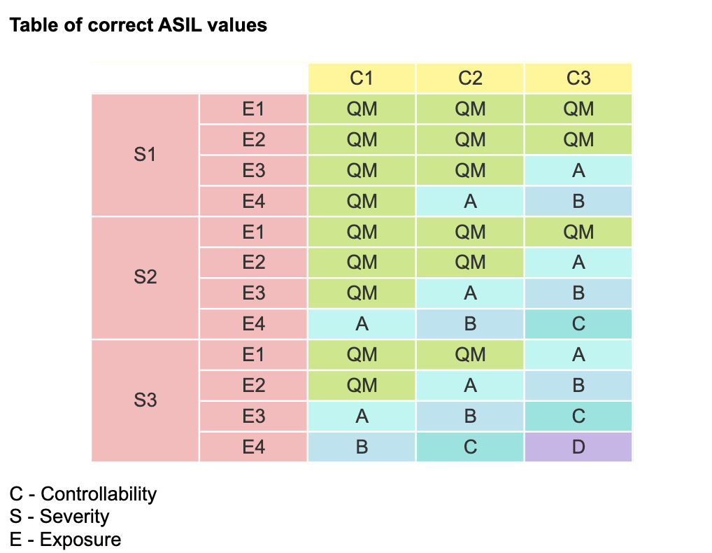
Table of correct ASIL values.

What are safety goals?

Safety goals are the level of safety required by an automotive component to function normally without posing any threats to the vehicle.

For example, for a car door, the safety goal could be both the importance of having it opened or closed depending on which action is safe under a particular condition.

Icon of blue car with opened door.

During instances of fire inside the vehicle or a flood, the safety goal would be to have the car door opened as quickly as possible so that the passengers can escape.

Icon of blue car with closed door.

On the contrary, while the vehicle is moving fast, the safety goal related to the door will be to remain closed. 

The accidental opening of the door of a moving car could lead to greater risks.

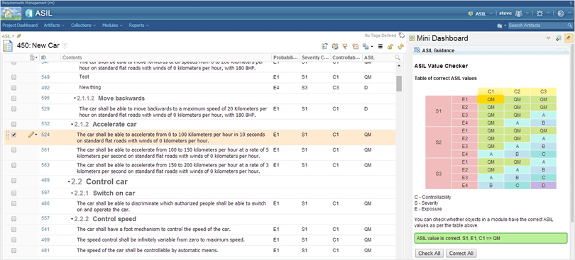
ASIL Value checker

IBM Rational DOORS Next Generation provides a client extension API that you can use to extend the functionality of the tool by using technologies that you already know, such as HTML and JavaScript. You can create and host a catalog of extensions on a server so that your team can share them.

The following image shows an extension that can check attribute values that are related to the ISO 26262 ASIL standard.

FMEA

Watch the following video, which shows how to capture failure mode and effects analysis in DOORS Next Generation using templates and extensions. 

If you want learn more read our article about FMEA

IBM Rational Solution for Automotive Engineering - HIS ASPICE (Beta)

This solution provides guidance and the means to capture and view an ASPICE assessment in real-time. It applies to HIS-ASPICE assessors and companies performing HIS-ASPICE assessments.

Capturing their current HIS-ASPICE capabilities levels allows them to easily determine gaps in their process. Implementation of HIS-ASPICE is helped and supported further by the adoption of the IBM CLM suite of tools. 

Learn by watching videos

Following is the series of videos with a discussion on how IBM tools can help with ASPICE compliance.

Hazard and Risk Analysis (HARA)

For any particular failure of a defined function at the vehicle level, a hazard and risk analysis (HARA) helps to identify the intensity of risk of harm to people and property. 

This Analysis can be provided only in the Requirements management tool (IBM Rational doors Generation) but also be modeled in the Modeling domain.

Icon of man working on laptop and above him is a screen with graph.

Model-Based Systems and Software Engineering for ISO 26262

BTC Embedded Systems AG provided the following documentation for the IBM® Rational® Rhapsody® Kit for ISO 26262, IEC 61508, IEC 62304, and EN 50128. In addition, the certificate and report for the certificate are also available for this Rational Rhapsody kit.

These documents are available in PDF format.

Note

Information concerning non-IBM products was obtained from the suppliers of those products, their published announcements, or other publicly available sources. IBM has not tested those products and cannot confirm the accuracy of performance, compatibility, or any other claims that are related to non-IBM products.

Document title and link Description
Rhapsody Kit for DO-178B/C Overview Provides an overview of the various artifacts in the Rational Rhapsody Kit for DO-178B/C.
IBM Rational Rhapsody Reference Workflow Guide Focuses on model-based development (MBD) with Rational Rhapsody in safety-related projects.
IBM Rational Rhapsody TestConductor Add On Reference Workflow Guide Describes a reference workflow for testing activities in a model-based development process using Rational Rhapsody and Rational Rhapsody TestConductor Add On. It complements the "IBM Rational Rhapsody Reference Workflow Guide."
IBM Rational Rhapsody TestConductor Add On Safety Manual Serves as a brief safety manual when using Rational Rhapsody TestConductor Add On for testing activities in a model-based development process when developing safety-related software.
IBM Rational Rhapsody TestConductor Add On Qualification Kit for DO 178B-C Overview Provides guidance to qualify Rational Rhapsody TestConductor Add On for DO-178B and DO-178C projects.
Readme file Provides instructions on which document to start with first.
Icon of green tree and graphs

Fault Tree Analysis

The Rational Harmony for Embedded RealTime Development process includes a best practice workflow called “eight steps to safety".
 
This practice is meant to be added on top of a general development process such as a traditional waterfall lifecycle or spiral model, such as the Rational Harmony for Embedded RealTime Development process. The basic practice steps are simple to understand and relatively straightforward to implement.

"8 steps to safety"

Icon of magnifying glass.
Icon of safety light.
Icon of hospital documents
Icon of list including green shield, which has check

1. Identify the hazards

2. Determine risks

3. Define the safety measures

4. Create safety requirements

Icon of paper, pencil and ruler
Icon of sketch of the process, with the pencil and cog.
Icon of the construction helmet and glasses.
Icon of the paper of checklist and pencil.

5. Create safe designes

6. Implement safety

7. Ensure the safety process

8. Test

The safety analysis in steps 1–3 are performed early in the development lifecycle and elaborated frequently throughout development. The safety analysis identifies the hazards presented by a system used in its execution context. This feeds back into the system requirements specification to ensure that the system, as specified, is safe.
 
The safety analysis results in a hazard analysis document that lists the hazards presented by the system, the faults that can lead to the hazard, the fault tolerance time of the hazard, the safety measure used to mitigate the hazard and the necessary fault handling response time.
 
Safety design specifies the means for detecting and extenuating the faults in the design. This is most commonly done by identifying the architectural and detailed design redundancy in such a way that the safety requirements are met. 
Image

1. Identify the hazards

Image

2. Determine risks

Image

3. Define the safety measures

Image

4. Create safety requirements

Image

5. Create safe designes

Image

6. Implement safety

Image

7. Ensure the safety process

Image

8. Test

The safety analysis in steps 1–3 are performed early in the development lifecycle and elaborated frequently throughout development. The safety analysis identifies the hazards presented by a system used in its execution context. This feeds back into the system requirements specification to ensure that the system, as specified, is safe.
 
The safety analysis results in a hazard analysis document that lists the hazards presented by the system, the faults that can lead to the hazard, the fault tolerance time of the hazard, the safety measure used to mitigate the hazard and the necessary fault handling response time.
 
Safety design specifies the means for detecting and extenuating the faults in the design. This is most commonly done by identifying the architectural and detailed design redundancy in such a way that the safety requirements are met. 
The Rational Harmony for Embedded RealTime Development process recommends this be done with the application of FTA to link the safety measures with the faults to ensure fault coverage. Safety testing is then performed to ensure that the safety requirements are met. 
 
This typically involves testing the primary functionality and quality of service testing used for non-safety-critical systems as well as seeding the system with faults. Seeded faults may be simulated, or they may be done by actually inducing the faults in the running system. It is common, for example, to cut wires, discontinue power and pull chips from sockets during fault seeding tests.

What is FTA?

As mentioned above, FTA is a common and useful analytic technique applied to safety-critical systems. In FTA, conditions leading up to hazards are logically analyzed for cause-effect relations using standard logical operators AND, OR, XOR, and NOT. Figure 3 shows the basic symbols used in the FTA diagrams.
 
FTA allows you to analyze the preconditions of hazardous conditions and how they combine with faults to result in hazards. When these relations are identified, you can add safety measures whose faults must be ANDed with the original fault to lead to the hazardous condition. In other words, to arrive at the hazardous condition, the original fault must occur AND there must be a fault in the safety measure as well. 
 
There is normally an assumption of single fault independence, which means that the primary and safety-measure faults are independent. When the faults are not independent, this is called a common-mode fault and usually means that the safety measure is inadequate for the need.

Automotive safety standards

ASPICE (Automotive Software Process Improvement and Capability Determination)

ASPICE is an extendable process assessment model for the automotive industry, focused on software development. IBM Solution ELM (Engineering Lifecycle Management) Automotive Compliance solution - a set of tools that combine IoT, AI, and analytics to manage the end-to-end engineering lifecycle in a scalable way.
 
Pre-defined assets for compliance and ASPICE; includes project dashboards, agile process guidance, and detailed reports HIS ASPICE (Beta) - This solution provides guidance and the means to capture and view an ASPICE assessment in real-time. It applies to HIS-ASPICE assessors and companies performing HIS-ASPICE assessments. 

ISO 26262

Defines functional safety as the “absence of unreasonable risk due to hazards caused by malfunctioning behavior of electrical/electronic systems”. For ISO 26262 compliance, a functional safety consultant identifies and assesses hazards (safety risks).
 
These hazards are then categorized based on their criticality factor under the Automotive Safety Integrity Level (ASIL) under ISO 26262.  IBM Solution IBM Rational Solution for Automotive Engineering - ISO-26262 is a set of best practices to help organizations develop products that must comply with the ISO-26262 functional safety standard.
 
The scope of these practices covers areas that are described by ISO-26262, relating to the management of functional safety, concept, system engineering, and software development. They have been developed to support the incremental adoption of processes, practices, and tools, thereby reducing the time to value for process improvement initiatives.

Automotive Safety Integrity Level (ASIL)

Is a risk classification scheme defined by the ISO 26262 - Functional Safety for Road Vehicles standard. The determination of ASIL forms the very first phase of automotive system development.  At this point, all potential scenarios of hazards and dangers are evaluated for a particular automotive component, the occurrence of which can be critical for vehicle safety.
 
The IBM Solution DOORS Next Generation provides a client extension API that you can use to extend the functionality of the tool by using technologies that you already know, such as HTML and JavaScript. You can create and host a catalog of extensions on a server so that your team can share them.

FMEA Definition FMEA (Failure Mode and Effects Analysis)

Is a method for identifying, defining, and removing potential product and manufacturing process failures. The IBM Solution Rational Failure Mode and Effects Analysis (FMEA) feature set enables the product development team to identify, define, and control the mitigation of risks while ensuring traceability between requirements, failure modes, and test cases.

FTA Definition Fault Tree Analysis (FTA)

FTA is a common and useful analytic technique applied to safety-critical systems. In FTA, conditions leading up to hazards are logically analyzed for cause-effect relations using standard logical operators AND, OR, XOR, and NOT.

What can we help you with?

Image

Softacus AG

Löwenstrasse 20
8001 Zürich
Switzerland
E-Mail: info@softacus.com
Tel.: +41 43 5087081
Fax: +41 43 344 6075 

VAT: CHE-108.817.809 MWST
D-U-N-S® Number 486800618

Image

Softacus GmbH

Westendstrasse 28
60325 Frankfurt am Main
Germany
E-Mail: info@softacus.com
Tel.: +49 69 34876544
Fax: +49 69 5830 35709

VAT: DE301903892
D-U-N-S® Number 313482703

Image

Softacus s.r.o.

Křídlovická 351/47A
603 00 Brno
Czech Republic
E-Mail: info@softacus.com
Tel.: +420 530333482
Fax: +41 43 344 6075

VAT: CZ07286333
D-U-N-S® Number 496165108

Image

Softacus s.r.o.

Tatranské nám. 3
058 01 Poprad
Slovakia
E-Mail: info@softacus.com
Tel: +421 911 083 612
Fax: +41 43 344 6075

VAT: SK2121388148
D-U-N-S® Number  2121388148

Offcanvas

Cookie Policy